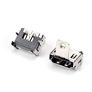


Display Port
Display Port Connector
● Product Specifications
| Current Rating: | 0.5 A | ||||||||
| Voltage Rating: | AC 40 V | ||||||||
| Contact Resistance: | Contact: 30mΩ Max.Shell: 50mΩ Max. | ||||||||
| Operating Temperature: | -20℃~+85℃ | ||||||||
| Insulation Resistance: | 100MΩ | ||||||||
| Withstanding Voltage | 500V AC/60S | ||||||||
| Max.Processing Temperature: | 260℃ for 10 Seconds | ||||||||
| Contact Material: | Copper Alloy | ||||||||
| Housing Material: | High Temperature Thermoplastic.UL 94V-0 | ||||||||
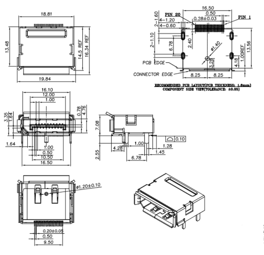
● Dimensional Drawings
● SCOPE
This Product Specification covers the mechanical, electrical and environmental performances requirements and test methods for pitch 1.0mm Display Port connector series products.
● DESIGN, CONSTRUCTION AND MATERIALS:
Connector shall be of the design, construction, physical dimensions and materials specified on the applicable sales drawing.
● PERFORMANCE AND TEST DESCRIPTION:
3.1 Performance requirement:Connector shall be designed to meet the electrical, mechanical and environmental performances requirements specified in paragraph 5
3.2 Rated Voltage: 40V AC
3.3 Rated Current: 0.5A
3.4 Operating Temperature Range: -20℃ to +85℃
● TEST REQUIREMENTS AND PROCEDURES
|
TEST ITEM |
TEST CONDITION |
REQUIREMENT |
| Appearance | Visual inspection | Meet the requirements of product drawing. No physical damage. |
|
ELECTRICAL PERFORMANCE |
||
| Low Level Contact Resistance | Mated connector, Contacts: measure by dry circuit,20mV Max,10mA.(EIA-364-23) Shell: measured by open circuit,5V Max,100mA. | Contact: 30mΩ Max.;
Shell: 50mΩ Max. |
| Dielectric withstanding Voltage | Unmated connectors, apply 500V AC (RMS.) for 1 minute between adjacent terminal or ground. Mated connectors, apply 300V AC(RMS.) for 1 minute between adjacent terminal or ground.(EIA-364-20) | No breakdown |
| Insulation Resistance | Unmated connectors, apply 500V DC between adjacent terminal or ground. Mated connectors, apply 150V DC between adjacent terminal or ground.(EIA-364-21) | 100MΩ Min.(Unmated),
10MΩ Min.(Mated) |
| Contact Current Rating | 55℃ Max. ambient, 85℃ Max. temperature change.(EIA-364-70, TP-70) | 0.5A Min. |
| Applied Voltage Rating | 40V AC(RMS.) continuous max., on any signal pin with respect to the shield. | No Breakdown |
| Electrostatic Discharge | Test unmated connectors from 1kVolt to 8kVolts in 1kVolt steps using 8mm ball probe. (IEC61000-4-2) | No evidence of discharge to contacts At 8kVolts. |
| Attenuation | 300KHz - 825MHz : -8db
828MHz - 2.475GHz : -21db 2.475GHz - 4.125GHz : -30db HDMI compliance test Specification Test ID 5-7 |
<-8db (300KHz - 825MHz)
<-21db (828MHz - 2.475GHz) <-30db (2.475GHz - 4.125GHz) |
| TMDS signals time domain impedance | Connector Area:
Type A:100Ω+-10% Transition Area: 100Ω+-10% Cable Area:100Ω+-5% |
100Ω +/- 10% |
| No discharge @8KV air @4KV contact | No discharge @8KV air @4KV contact | No evidence of discharge |
|
MECHANICAL PERFORMANCE |
||
| Insertion Force/ Withdrawal Force | Insert and withdraw connectors at a rate of 25±3mm per minute (EIA-364-13) | Insertion Force: 44.1N Max.; Withdrawal Force: 9.8~39.2N; |
| Latch Strength | Mated connector, apply axial pull-out force in the axial direction at the speed rate of 13mm/minute until the latch is disengaged or damaged.(EIA-364-98) | Pull force: 49.0N Min. No Damage on both connectors. |
| Terminal Pull-out Force | Assemblied in the housing at a rate of 25±3 mm per minute | 2.94N Min. |
| Durability | Measure contact and shell resistance after the following. Automatic cycling: 10000 cycles at 100±50 cycles per hour (EIA-364-09) | Contact Resistance:
Contact: Change from initial value = 30mΩ Max.; Shell: Change from initial value = 50mΩ Max. |
| Virbration | Amplitude: 1.52mm P-P or 147m/s2{15G} Sweep time: 50-2000-50 Hz in 20minutes. Duration: 12times in each X,Y and Z axes(total of 36times) . Electrical load: DC 100mA current shall be flowed during the test. (EIA-364-28 Condition III Method 5A) | Contact Resistance: Contact: Change from initial value = 30mΩ Max.; Shell: Change from initial value = 50mΩ Max. |
|
ENVIRONMENTAL PERFORMANCE |
||
| Thermal Shock | 10 cycles of: a)-55℃ for 30 minutes; b)+85℃ for 30 minutes; (EIA-364-32, Condition I) | Contact Resistance:
Contact: Change from initial value = 30mΩ Max.; Shell: Change from initial value = 50mΩ Max. |
| Low temperature | No any physical damage and electrical abnormal
Temperature : -25 degree Duration : 250 hours |
No any physical damage; Contact Resistance: Contact: Change from initial value = 30mΩ Max.; Shell: Change from initial value = 50mΩ Max. |
| Salt Spray | Subject mated connectors to 35+/-20C and 5+/-1% salt condition for 48hours. After test, rinse the sample with water and recondition the room temperature for 1 hour.(EIA-364-26B) | No detrimental corrosion allowed in contact area and base metal exposed. |
| Humidity | (A) Mated connectors together and perform the test as follows: Temperature: +25 to +85℃; Relative Humidity: 80 to 95%; Duration: four cycles(96 hours); Upon completion of the test, specimens must be conditioned at ambient room conditions for 24 hours, after which the specified measurements must be performed(EIA-364-31) | No Damage; Contact Resistance: Contact: Change from initial value = 30mΩ Max.; Shell: Change from initial value = 50mΩ Max. |
| (B) Unmated connectors together and perform the test as follows: Temperature: +25 to +85℃; Relative Humidity: 80 to 95%; Duration: four cycles(96 hours); Upon completion of the test, specimens must be conditioned at ambient room conditions for 24 hours, after which the specified measurements must be performed(EIA-364-31) | No Damage; Conform to item of Dielectric Withstanding Voltage and Insulation Resistance | |
| Thermal Aging | Mated connectors and expose to +105±20C for 250 hours. Upon completion of the exposure period, the test specimens shall be conditioned at ambient room condition for 1to2 hours, after which the specified measurements shall be performed. (EIA-364-17,condition4,method A) | No Damage; Contact Resistance: Contact: Change from initial value = 30mΩ Max.; Shell: Change from initial value = 50mΩ Max. |
| Solder-ability | Dip solder tails into the molten solder (held at 245±3℃) up to 1.2mm from the bottom of the housing for 3~5 seconds. | 95% of immersed area must show no voids, pin holes |
| Resistance to Soldering Heat | Refer soldering method ; The conditions specified on paragraph 5 shall be repeated twice | No Damage |
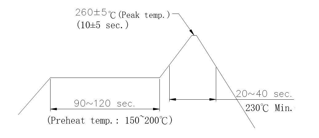
● RECOMMENDED INFRARED REFLOW CONDITION:
Temperature Condition Graph
● TEST SEQUENCE
|
Item |
Test Group |
|||||||||
|
G1 |
G2 |
G3 |
G4 |
G5 |
G6 |
G7 |
G8 |
G9 |
G10 |
|
| Appearance |
1,4 |
1,5,9 |
1,5,8 |
1,3 |
|
1 |
1,4 |
1,4 |
1,4 |
1,4 |
| Low Level Contact Resistance |
2,5 |
2,6,10 |
6,9 |
|
|
|
2,5 |
2,5 |
|
2,5 |
| Dielectric Withstanding Voltage |
|
|
2 |
|
|
|
|
|
|
|
| Insulation Resistance |
|
|
3 |
|
|
|
|
|
|
|
| Contact Current Rating |
|
|
|
2 |
|
|
|
|
|
|
| Applied Voltage Rating |
|
|
|
4 |
|
|
|
|
|
|
| Electrostatic Discharge |
|
|
|
|
|
4 |
|
|
|
|
| T.M.D.S signals Time Domain impedance |
|
|
|
|
|
2 |
|
|
|
|
| Attenuation |
|
|
|
|
|
3 |
|
|
|
|
| Insertion Force/ Withdrawal Force (no latches ) |
|
3,7,11 |
|
|
|
|
|
|
|
|
| Latch Strength |
|
(6) |
|
|
|
|
|
|
|
|
| Terminal Pull-out Force |
|
|
|
|
1 |
|
|
|
|
|
| Durability |
|
4,8 |
|
|
|
|
|
|
|
|
| Virbration |
3 |
|
|
|
|
|
|
|
|
|
| Thermal Shock |
|
|
4 |
|
|
|
|
|
|
|
| Low temperature |
|
|
|
|
|
|
|
|
|
3 |
| Humidity |
|
|
7 |
|
|
|
|
|
|
|
| Thermal Aging |
|
|
|
|
|
|
3 |
|
|
|
| Salt Spray |
|
|
|
|
|
|
|
3 |
|
|
| Solder-ability |
|
|
|
|
|
|
|
|
2 |
|
| Resistance to Soldering Heat |
|
|
|
|
|
|
|
|
3 |
|
| Number of Sample (SETS) |
2 |
2 |
2 |
2 |
2 |
2 |
2 |
2 |
2 |
|
NOTES: Numbers indicate sequence in which tests are performed.