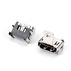


USB Connector
USB-A Connector
● Product Specifications
| Current Rating: | 1.5 A | ||||||||
| Voltage Rating: | AC 30 V | ||||||||
| Contact Resistance: | 30mΩ Max | ||||||||
| Operating Temperature: | -20℃~+85℃ | ||||||||
| Insulation Resistance: | 1000MΩ | ||||||||
| Withstanding Voltage | 500V AC/60S | ||||||||
| Contact Material: | Copper Alloy | ||||||||
| Housing Material: | Thermoplastic.UL 94V-0 | ||||||||
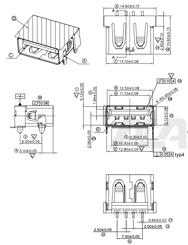
● Dimensional Drawings
● SCOPE
This Product Specification covers the mechanical, electrical and environmental performances requirements and test methods for USB A TYPE UPRIGHT REVERSE (Universal Serial Bus Revision 2.0) CONNECTOR.
● PRODUCT DESCRIPTION
2.1 Design and Construction
Construction and physical dimensions shall be specified on the applicable sales drawing. Connector consists of a metal shell, a plastic housing, and 5 terminals.
2.2 Materials and Plating
Refer to respective CTL sales drawings for information on materials, plating and marking.
● APPLICABLE DOCUMENTS
In the event of conflict between the requirements of this specification and the sales drawing, the sales drawing shall take precedence. In the event of conflict between the requirements of the specification and the referenced documents, this specification shall take precedence.
3.1 Rating
Rated Voltage (Max.): 30V AC(rms)
Rated Current (Max.): 1.5Amps
Operating Temperature Range: -55℃ ~ +85℃
● Test Requirements ELECTRICAL,MECHANICAL & ENVIRONMENTAL)
|
ELECTRICAL REQUIREMENTS |
||
|
TEST ITEM |
TEST CONDITION |
REQUIREMENT |
| Low Level Contact Resistance | EIA-364-23
Mate connectors: apply a maximum voltage of 20 mV and a current of 100 mA |
30 mΩ Max.. |
| Insulation Resistance | EIA-364-21
Unmate & unmount connectors: apply a voltage of 500 VDC between adjacent terminal and between terminals to ground. |
1000 MΩ Min. |
| Dielectric Withstanding Voltage | EIA-364-20
Un-mate connectors: apply a voltage of 500 VAC for 1 minute between adjacent terminal and between terminals to ground. |
No Breakdown;
Current leakage < 0.5mA |
| Contact Current Rating | EIA-364-70
Mate connectors: measure the temperature rise at the rated current (1.5A) |
Temperature rise: 30℃ Max. |
| Contact Capacitance | EIA-364-30
Test between adjacent circuits of unmated connectors at 1MHz. The object of this test is to detail a standard method to determine the capacitance between conductive elements of a USB connector. |
2pF Max.. per Contact |
|
MECHANICAL REQUIREMENTS
|
||
|
TEST ITEM |
TEST CONDITION |
REQUIREMENT |
| Connector Mate And Un-mate Force | EIA-364-13
Mate and un-mate connector (male to female) at a rate of 20 mm per minute |
Mating force:35N Max.;
Un-mating force:10N Min.; |
| Durability | EIA-364-09
Mate / un-mate Connector assemblies for 1500 cycles at max. rated of 300 cycles per hour. |
Shall meet visual requirement, show no physical damage |
| Vibration
(Random) |
EIA-364-28
Test condition VII Mate connectors and vibrate |
Appearance: No Damage;
Discontinuity: 1microsecond Max. |
| Mechanical Shock | EIA-364-27 Test Condition H
Subject mated connectors to 30G’S half-sine shock pulses of 11 ms duration. Three shocks in each direction applied along three mutually perpendicular planes, 18 total shock.. |
Appearance: No Damage;
Discontinuity: 1microsecond Max. |
|
ENVIRONMENTAL REQUIREMENTS |
||
|
TEST ITEM |
TEST CONDITION |
REQUIREMENT |
| Humidity | EIA-364-31 method III
Subject mated connectors to 60 cycles temperature between -25℃ to +65℃ with 90 to 95% RH |
Visual: No Damage;
Insulation Resistance: 1000MΩ Min. Dielectric Strength: No Breakdown at 500 VAC |
| shock (Thermal) | EIA-364-32, Test Condition I
Subject mated connectors to ten cycles between -55℃ to +85℃ |
Visual: No Damage;
Insulation Resistance: 1000MΩ Min. Dielectric Strength: No Breakdown at 500 VAC |
| Temperature Life | EIA-364-17 Test Condition 2 Method A
Subject mated connectors to temperature life at 85℃ for 500 hours |
Appearance: No Damage;
Contact Resistance: 30mΩ Max.; |
| Solder-ability | EIA-364-52
After one hour steam aging. |
Solder Wetting: 95% of immersed area must show no voids or pin holes |
| Resistance to solder heat | MIL-STD-202F, Method 210A, Test Condition B. for WAVE SOLDERING Pre-heat: 80℃, 60 Seconds
Temperature: 265 ± 5 ℃ Immersion duration: 10 ± 1 sec. |
No mechanical defect on housing or other parts. |
● TEST SEQUENCE
| Test Description |
A |
B |
C |
D |
E |
F |
| Examination of product |
1,9 |
1,5 |
1,9 |
1,3 |
1,3 |
1,3 |
| Contact Resistance |
3,7 |
2,4 |
|
|
|
|
| Insulation resistance |
|
|
3,7 |
|
|
|
| Dielectric Withstanding Voltage |
|
|
4,8 |
|
|
|
| Contact Capacitance |
|
|
2 |
|
|
|
| Contact Current Rating |
|
|
|
|
2 |
|
| Mating & Un-mating Force |
2,8 |
|
|
|
|
|
| Durability |
4 |
|
|
|
|
|
| Vibration |
6 |
|
|
|
|
|
| Mechanical Shock |
5 |
|
|
|
|
|
| Humidity |
|
|
5 |
|
|
|
| Thermal Shock |
|
6 |
|
|
|
|
| Temperature Life |
|
3 |
|
|
|
|
| Solder-ability |
|
|
|
2 |
|
|
| Resistance to soldering heat |
|
|
|
|
|
2 |
| Number of sample |
5 |
5 |
5 |
5 |
5 |
5 |
Note:
l Samples shall be prepare in accordance with applicable manufacture’s instructions and shall be selected at random from current production.
l Precondition samples with 3 cycles durability.
l All the test shall be performed in the sequence.
● PACKAGING
Parts shall be packaged to protect against damage during handling, transit and storage.
Receptacles will be supplied in tape and reel.